1.1) Introduction
Before starting to read this, please be aware that some of the ideas stated here are unproven and may be wrong, but then again, they may just be right! This is not an article for the beginner or the student but is intended to stimulate experienced engineers into re-thinking what they already know about electrons. It starts off by asking a number of silly schoolboy type questions that arise from a curiosity for solid knowledge. It then suggests some behaviours that may be more valid than present thinking and some could eventually be accepted by the electronic engineering community as more practical behavioural models.
One of the checks that we can do in the study of charged particles to prove that we have our theories right, is to ensure that the presently accepted models of electron behaviour are consistent within more than one explanation of component behaviour. There still seems to be differences within our present understandings and sometimes complete omissions of the behaviour of electrons with some components and this article highlights a few of them. This article does not follow the pattern of our other technical articles on this website which use measurement, data analysis, graphs and formulas to give positive evidence of component behaviour, because either it is too difficult to make the required measurements or there is currently no known way to perform the related measurements. Instead, this article presents a series of questions about present theory in a selection of components and then introduces new theoretical models that are more consistent with the behaviour across the selected components.
Currently accepted characteristics of an electron:-
direction of electron current flow is negative to positive
charge (Q) -1.602176634 x 10⁻¹⁹ Coulombs
mass (me) 9.10938371 x 10⁻³¹ kg
speed in a vacuum 299,792,458 m/s (approximately 3 x 10⁸ m/s) or the speed of light (c)
magnetic dipole
electric monopole
1.2) Direction of Current Flow
When I was a young boy, I spent many happy hours playing with bits of wire, batteries, accumulators, motors, lamps, switches and anything that I could get my hands on in order to study how they reacted to this invisible thing called electricity. I was told that electricity flowed from positive to negative (conventional current flow) and was quite happy with this. Later my elder brother joined the RAF and studied electricity. He explained to me that in an ac circuit, the electricity flowed first in one direction through the circuit and then reversed and flowed in the opposite direction. This seemed plausible and I was again happy with the explanation. On starting employment within the electronics industry, I was told that electrons have a negative charge and flow from negative to positive (electron flow) and that they had got the facts wrong when it was first decided that the direction of flow was from positive to negative. This was bad news for me, what convention should I use? As time went on it became obvious that all of the circuit diagrams were drawn in such a way that it was easiest to think of current flowing from positive to negative (conventional current flow) and I just settled with this and was happy to just think in this way. At a much later date I was introduced to the Vector Network Analyser and this changed my thinking entirely. It became obvious that signals could be sent down a coaxial cable in one direction and that if they met a mismatch they were reflected back in the opposite direction, within the same cable. Knowing that the signal used has both a positive and negative half cycle (sine wave) it now became known to me that the charged particles in a coaxial cable flow in the same direction whether they were positive or negative and simply went in the direction that they were launched. It is not correct to think of electrons flowing from positive to negative or negative to positive in all circumstances, but it does seem to fit the behaviour of simple dc circuits.
1.3) Negative and Positive Charge
The modern thinking is that electrons have a negative charge and that positive charges are conveyed by positrons, protons or ions. That the negative electrons can flow easily in a conductor because there are already lots of free electrons. Also that positive ions can flow in fluids from positive to negative and that positive protons can flow in a plasma from positive to negative.
The charge on an electron was measured in 1909 by R A Millikan with an oil drop experiment. By measuring the force required to suspend an oil drop in mid-air, he concluded that the charge on an electron negative and estimated it to be -1.5924(17)×10−19 Coulombs. It is interesting to note that when T A Edison was told that the charge on an electron was finite, he stated that he had always thought that the charge on an electron was infinitely variable.
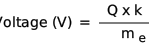
If all electrons have a constant mass of 9.109 x 10⁻³¹ kg and a constant charge of -1.602176634 × 10⁻¹⁹ Coulombs, then they logically must all have the same constant negative voltage!
Where
Q is the charge in Coulombs
k is a constant
me is the electron mass in kg
So, any voltage other than the constant negative electron voltage must be conveyed by positrons, protons, ions or some other particle. Why do we bother about thinking of electrons at all when the vast majority of particles cannot be electrons which only have one finite negative voltage?
The statement that electrons only have a negative charge becomes a problem when an ac signal passing down a coaxial cable is studied. A good quality coaxial cable can have a velocity factor of approximately 0.82, meaning that the electrons are travelling near the velocity of light. Does this mean that for the positive voltage half of a sine wave we have positrons, protons or ions travelling near the speed of light? Does it also mean that there are lots of free positrons, protons or ions in a conductor? Then what about the negative cycle where only one negative voltage can be electrons? What other particles carry all of the other negative Voltages?
The matter becomes more complex when electron behaviour in an inductance is examined. The basic accepted principle of an inductor is that a current passing through a wire produces a magnetic field around the wire. When this magnetic field collapses, a back EMF is generated which has the opposite potential to the original applied voltage. This is indeed intriguing, are negative electrons turned into positive positrons, ions or protons and vice versa.
Another interesting example is a coupling capacitor that is used as a dc block. Say it is coupling the ac output of an audio amplifier that is driving a loud speaker that has a low dc resistance. If the amplifier is supplied with -20 volts and the output stage is class A, then the dc input (quiescent voltage) to the capacitor will be -10 volts. On switch on, the capacitor charges and then blocks the dc, so the capacitor output sits at 0 volts with no signal present. When a large signal is applied to the amplifier input, the output of the amplifier at the capacitor input swings from approximately -20 volts to 0 volts and the capacitor should therefore be fed with electrons (and other particles?). When the signal reaches the other side of the capacitor, the output swings from -10 volts to + 10 volts. Does this mean that the capacitor has conducted the electrons on the negative output and converted the negative electrons to positive positrons, ions or protons on the positive output?
When a reflection from a short circuit termination on a coaxial cable is considered, the problem is similar to an inductor. A short circuit termination produces a phase change of 180°. Is this phase change achieved by the negative charge from the electron forming a magnetic field and then when the magnetic field collapses a different particle with a positive charge is formed, similar to the basic operation of an inductor? The process being reversed for a particle that starts off positive and turns into a negatively charged electron? Our present models of particle flow just do not fit to these inductor, capacitor and coaxial cable examples when the particles are considered to be electrons, positrons and ions and so something must be wrong!
1.4) Velocity Constant in a Coaxial Cable
After searching reference books and the Internet it appears that there is no explanation for the mechanism that causes delay variations within different types of coaxial cables. If we measure the delay with a VNA in one metre of RG-8X we would find it to be approximately 4 ns, giving a velocity factor of 0.82, whereas one metre of RG-213 would give approximately 5 ns or a velocity factor of 0.66. If we joined the two cables together, such that the signal first passes through the slower cable and then through the faster cable (RG-213 then RG-8X), the measured delay would be 9 ns. How can this happen if the electrons have been slowed down by the first cable? The laws of energy conservation say that there would have to be energy added in the second cable to speed the electrons up again, but there is no extra energy applied to the cable and it is a passive device.
1.5) What happens to the charged particles in an antenna?
If we now compare the behaviour of the antenna to an inductor there is a contradiction. The magnetic field for an inductor always collapses inwards and generates an electric current with very high efficiency, suggesting that virtually all of the magnetic field collapses inwards. Whereas, in the present theory for an antenna the radiated magnetic then subsequent electric and magnetic fields are said to collapse outwards, just how does the electron/charged particle know what is required of it and whether it should form a magnetic field that collapses inwards like in an inductor or outwards like in an antenna?
Present theory suggests that antennas are supplied with large numbers of charged particles, but there are no particles emitted by the antenna. Just what happens to these particles, are the charges spent (radiated) and then the uncharged particles drift back out of the antenna towards the transmitter or are the particles accumulated by the antenna? If the charged particles going into an antenna are negative electrons during the negative phase and positive protons during the positive phase, this accumulation would make hydrogen gas. Does this mean that antennas discharge hydrogen gas as they are radiating? If so, is this the cause of the burning damage as seen in a corona discharge? By calculation, an output power of 10,000 Watts gives 2.5 kg of hydrogen over the period of one year. Does this mean that high power antennas are prone to sporadic burning or even explosions?
If the charged particles going into an antenna are electrons and ions these would presumably combine and become full atoms. Would these atoms then form large deposits on the exterior of the antenna and if so what material would these deposits consist of? I can imagine a scene, it is a cold rainy night and a huddle of radio hams are having one of their regular meetings in an old radio shack. They are all sat around an ancient one bar electric fire that Fred rescued from a skip. The element of the fire had been burnt out so Bert rewound it with some resistance wire which he bought for five pence at a car boot sale. The resistance is too high so the element now only gives 100 Watts and no longer glows red, but everybody is happy with this because of the saving in electricity. They all have steaming mugs of tea all made with the one tea bag that is fresh this month. The subject of conversation is antenna warts. Richard starts it off with recollections of one of his old pals rigs. "It was amazing, he only had an OC71 as the output stage but he got ten watts out of it and could reach right round the world. Then he found he had a three-and-a-half-pound antenna wart that was formed of pure gold. He said that the jewellers had never seen such purity. He lives in the Bahamas now and has a whole antenna farm growing wart gold, but he reckons that the warts play havoc with the VSWR." Hmm!
2.1) Alternative Explanations
How can we explain all of these anomalies with the present theories of electron behaviour? There must be some errors but which explanations are correct? My personal preference is to only believe those things that I can actually measure but most of the behaviour mentioned does not have any known measurement methods. The judgement of what is correct then becomes subjective and influenced by personal opinion, becoming a belief rather than real knowledge. By taking the behaviour of various components that I have personally proven with a high level of certainty and then adding all of the component behaviours that fit with these proven ones, the uncertain behaviours become more noticeable. I shall now discuss these selected behaviours in more detail.
2.2) Direction of particle flow
It is not difficult to prove particle flow in a transmission line with an oscilloscope. Simply connect a T piece to Channel 1 and connect one of the T piece inputs to the calibrator output using a short piece of coaxial cable and observe the square wave. Then connect the remaining T piece input to Channel 2 of the oscilloscope using a very long length of coaxial cable and observe that the Channel 2 square wave is delayed from the Channel 1 square wave. This proves that the electrons are flowing along the transmission line from Channel 1 to Channel 2.
If the input from the oscilloscope calibrator is now transferred to a sine wave generator set to 2 Volts pp, the oscilloscope will now display sine waves with Channel 2 still delayed from Channel 1. Thus proving that the particles flow in the direction that they are launched, they do not just flow from negative to positive.
Further proof could then be gained by replacing the sine wave generator with a single 1.5 cell (normally wrongly called a battery) and observing the resultant change of voltage when you reverse the cell polarity (but you will need to get the oscilloscope triggering right).
So, do the particles flow from negative to positive in a short wire fed with dc? I have yet to see a good argument or a measurement method for that and I reserve my judgement. It was shown in the Standing Waves and Reflection article that the particles in a transmission line align according to their North and South poles. This alignment is analysed for all combinations of mismatch reflection and positive/negative particle charges and to my logic, is also proof of electron flow direction because it uses a model where the electrons leave the transmitter, travel along the transmission line and if they meet a mismatch, they are reflected back towards the transmitter.
2.3) Charge on an Electron
If the above paragraphs are explained using the principle that the electron has an infinitely variable charge, then everything related to charge fits! There is no need for ions or protons to be able to pass through a conductor. Inductors do not have to change ions or protons to electrons and vice versa. Capacitors do not have to change ions or protons to electrons and vice versa. Coaxial cables also do not have to convert the charged particles either.
After the oil drop measurement made by Robert A. Millikan, which can be seen at Oil drop experiment , he deduced that there is a negative charge on an electron and estimated a figure of 1.592 x 10⁻¹⁹ Coulombs. This charge has been accepted (with improvements in accuracy) as the charge on all electrons.
A look at Millikan's equations (also found in other various publications on the Internet) are given here in a simplified form and they might reveal something suspicious to the inquiring mind.
Fup = Fdown
Fup = Q x E
Fdown = m x g
Q x E = m x g
Q = m x g / E
Where:-
Q is the charge on an electron
E is the electric field of an electron
m is the mass of the oil droplet
g is gravity
When you look at the equations, they start well with the upward force being equal to the downward force. Then it starts to go astray with the upward force being an electrical charge and the downward force being kinetic energy generated from a mass being pulled down by gravity. There is no mention of the downward force of gravity on the electrons. The electron charge is assumed to repel the oil drop but if you rub a balloon on your clothing giving it an electric charge, the balloon will then stick on the ceiling which has not received a charge, thus showing that the generated electrical charge difference is a force of attraction. Furthermore it is assumed that an oil drop will react to an electrical field without any proof.
If we compare the situation with something larger, say the oil drop becomes a football and the electrons become peas shot out of pea shooters at a constant speed. Could the peas support the football and suspend it above the ground even if the football and the peas were at the same electrical potential? Of course they could and electric charge does not come into the equation. The equation would then become something like this:-
Fup = Fdown
Fup = mp x Sp / g
Fdown = mf x Sf x g
mp x Sp / g = mf x Vf x g
Where:-
mp is the total mass of all the peas
Sp is the speed of the peas
mf is the mass of the footballs
Sf is the speed of the football
g is gravity
From this equation we can find an unknown from three knowns but there is no electrical charge involved. Why then cannot the Millikan oil drop experiment actually be revealing that electrons have a constant mass and not that they have constant charge. The Millikan experiment may really just give the kinetic force present in an electron after emission. It does not make sense that this force represents the electric charge on all electrons in relation to all other bodies at all times.
2.4) Three Blocks of Copper
Let's expand this still further, again with something akin to Einstein's thought experiments. Assume that there are three blocks of copper standing on an insulating surface and we charge one block to +100 Volts with respect to ground another block to -100 Volts with respect to ground and leave the third uncharged (0 Volts). We now remove one electron from each of the blocks and measure their charges. As the mass of each electron is the same because electron mass is supposedly constant, the voltage on each electron will be constant because it will be proportional to the charge which Millikan declared to be constant. Would the electron removed from the block at zero volts have any voltage on it? Well, according to Millikan's theory it would have a negative charge and we would expect a negative voltage w.r.t. ground. Now if we observe the voltage on the electron removed from the block charged to +100 Volts what voltage would we expect the electron to posses w.r.t ground? Does it somehow have the exact same voltage as the electron removed from the block at ground potential? Common sense would suggest that it would be 100 Volts positive in relation to the electron removed from the block at ground potential. If common sense is correct, we immediately have two electrons at different potentials. It then follows that the electron from the block at -100 Volts would be at 100 Volts below the electron removed from the block at ground potential. This not only means that the electrons can be at different potential but also that if the starting voltages on the blocks are adjusted appropriately we can have electrons that are positive or negative w.r.t. ground.
2.5) Modifying The Charge
Additionally, there appears to be no reason why the charge on an electron cannot be modified once the electron has been separated from the conductor. If the electron passes through a highly charged electric field it would be expected that the electron could retain some of the high charge from the electric field. Our perception of an electron always having a finite negative charge is far too simplistic and needs revising. Whatever the actual explanation of the charge on an electron may be, there is an anomaly in many perceived behaviours and the classical understanding of electrons and charged particles which needs correcting if our knowledge is to advance.
Technical Articles Index First Published on 21/10/2026 by William J Highton