4.8) Alignment of Electrons Travelling In a Conductor
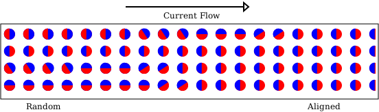
It has now been demonstrated with an extremely close analogy that as the electrons flow in a conductor carrying a dc current, at some point they become aligned with their magnetic poles in line with the current flow and always polarised with their South poles at the leading edge as in Figure 22. The fact that it is one specific pole at the leading edge is confirmed by the observation that the compass is always deflected in a specific direction and this is also defined by Maxwell's Right Hand Grip Rule. Note that the compass deflects at approximately right angles to the conductor because the electrons are in motion and if the electrons were stationary the compass needle would be in line with the conductor the same as the compass needle aligned with the Spherical Magnets on the wheel in Figure 20.
Figure 22 Electrons Flowing in a Conductor
5.1) Electron Polarisation While Passing Through a Toroid
We have one more fact to establish in order to understand the polarisation of the electrons in a Transmission Line, that is the polarisation of the reflected electrons within the Transmission Line after they are reflected from a mismatched termination. This can be deduced from previous measurements and some simple logic tests. It has been shown in Para 3.5 that when two currents, of the same phase and same polarisation (because there were no reflections), pass through a toroid in the same direction, they summed. Whereas, if the currents were in opposite directions they subtracted. A very simple observation but one that is essential in understanding how Standing Waves appear to be present in Transmission Lines. These measurements are illustrated in Figures 23 and 24 below and the large green ticks indicate that these logical tests agree with the previous observations in Para 3.5.
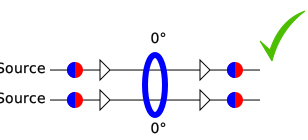
Phase Difference = 0°
Polarisation = 0°
Total = 0°
Result = SUM
Figure 23 Aligned Electrons
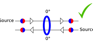
Phase Difference = 0°
Polarisation = 180°
Total = 180°
Result = DIFFERENCE
Figure 24 Opposing Electrons
5.2) Current Related Electron Polarisation in an Open Transmission Line
The above observations can now be applied to the plot of the Current Standing Wave in an OPEN in Figure 6 on Page 1 which gives a Sum Current at 90°. Compare this with Figure 25 which shows a phase shift of 90° in the Forward direction from the ferrite towards the OPEN and 90° in the Reflected direction giving a total of 180° phase shift. However, the electrons have been rotated by the OPEN and are in the opposite polarisation, so the currents are summed in the ferrite. Thus the logic is confirmed and marked with a green tick. In contrast, Figure 26 shows the electrons remaining in the same polarisation and the logic test fails with a big red cross. Some readers may find it less confusing to ignore the incorrect polarisation Figures that are all marked with a large red cross.
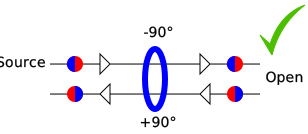
Phase Difference = 180°
Polarisation = 180°
Total = 360°
Result = SUM
Figure 25 Opposing Electrons
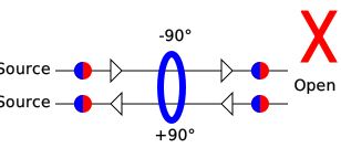
Phase Difference = 180°
Polarisation = 0°
Total = 180°
Result = DIFFERENCE
Figure 26 Aligned Electrons
We will continue to examine all of the remaining combinations of Voltage into an OPEN then Current and Voltage into a SHORT to ensure that the rules hold true for all measurement results.
5.3) Voltage Related Electron Polarisation in an OPEN Transmission Line
The above observations can also be applied to the plot of the Voltage Standing Wave in an OPEN in Figure 5 Page 1 which gives a Difference Voltage at 90° from the termination. Figure 27 shows there is a phase shift of 90° in the Incident direction and 90° in the Reflected direction giving a total of 180° phase shift. In this case the measured electrons pass through the voltmeter in the same direction and aligned polarisation causing the Voltmeter currents to add and indicate a resultant Voltage difference. Figure 28 is then shown to demonstrate that the Reflected electrons cannot be of opposed polarisation and opposite phase to produce a Difference Voltage.
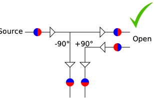
Phase Shift = 180°
Polarisation = 0°
Total = 180°
Result = DIFFERENCE
Figure 27 Aligned Electrons
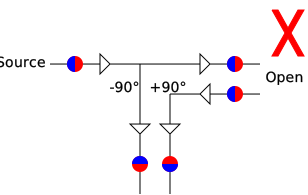
Phase Shift = 180°
Polarisation = 180°
Total = 360°
Result = SUM
Figure 28 Opposing Electrons
5.4) Standing Waves in a SHORTED Transmission Line
The effect of a SHORT termination on a Transmission Line is now brought into consideration by utilising the same logical test methods applied to the OPEN Termination. These must also be true for the SHORT Termination in order to confirm that the complete analysis is correct.
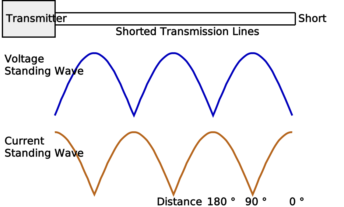
Figure 29: 'Standing Waves' along a Transmission Line into a SHORT
5.5) Current Related Electron Polarisation in a SHORTED Transmission Line
The above observations are yet again applied but this time to the plot of the Current Standing Wave in a SHORT as in Figure 29 above, which gives a Difference Current at 90°. Figure 30 shows there is a phase shift of 90° in the Incident direction and 90° in the Reflected direction giving a total of 180° phase shift. However, the electrons from a SHORT are in the aligned polarisation which results in a current difference in the ferrite. Figure 31 is then shown to demonstrate that the Forward and Reflected electrons cannot be oppositely aligned to produce a Difference current.
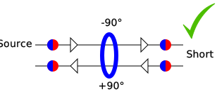
Phase Difference = 180°
Polarisation = 0°
Total = 180°
Result = DIFFERENCE
Figure 30 Aligned Electrons
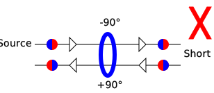
Phase Difference = 180°
Polarisation = 180°
Total = 360°
Result = SUM
Figure 31 Opposing Electrons
5.6) Voltage Related Electron Polarisation in a SHORTED Transmission Line
Lastly, similar observations are applied to the plot of the Voltage Standing Wave into a SHORT as shown in Figure 29 above which shows a Sum Voltage at 90° from the termination.
Figure 32 shows there is a phase shift of 90° in the Forward direction and 90° in the Reflected direction giving a total of 180° phase shift. In this case the Electrons pass through the Voltmeter in the same direction, have opposite polarisation and 180° phase shift, which causes the two currents to sum in the Voltmeter and indicate a doubling of Voltage. This doubling of voltage is not real and there is no obvious mechanism to transfer charge between electrons to produce a higher voltage but the mechanism for doubling the current is plain to see. The apparent Voltage doubling is a result of the Voltmeter being calibrated to indicate the correct Voltage for a single current but the current has doubled, so the Voltmeter indicates a doubled Voltage.
Figure 33 is shown to demonstrate that the Electrons passing through the Voltmeter cannot be of the same polarisation to produce a Voltage Sum.
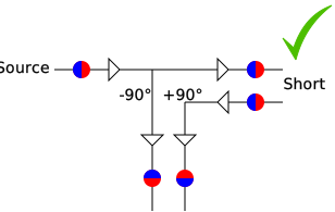
Phase Shift = 180°
Polarisation = 180°
Total = 360°
Result = SUM
Figure 32 Opposing Electrons
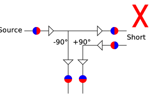
Phase Shift = 180°
Polarisation = 0°
Total = 180°
Result = DIFFERENCE
Figure 33 Aligned Electrons
5.7) Voltmeter Voltage Doubling Mechanism
In order to understand the Voltage doubling mechanism we refer to the moving coil meter type, which were used in high-end multimeters, to give a probable explanation. These meters had a needle that moved against springs. The moving coil itself had a fairly low resistance and was only suitable for low Voltage measurements without additional circuitry. The presence of the springs caused the meter to require considerably more energy to compress the springs at the high end of the scale than the lower end and thus requires considerably more Current. This meant it was, in reality, a Power meter that was calibrated in Volts. They got around this problem by compressing the Voltage scale at the high end and quoting the input resistance in Ohms/Volt but it was still in reality a Power Meter. In order to measure higher Voltages a high value resistor was placed in series with the moving coil meter and sometimes another scale added in order to give a calibrated reading.
When the two separate Currents from the Forward Wave and the Reflected Wave in a Transmission Line arrive at the Voltmeter, they behave as two totally separate Currents and they both split from the main Currents according to the equations for Reflection Coefficient and the total resistance of the meter and any series resistance. The input Voltage is then divided by the meter and resistor potentiometer if the resistor is present. The division being according to the resistance ratio which is also the power ratio. This means that the meter receives the correct Voltage for a single Current but actually has twice the Current and being basically a Power meter and having double the input Power because the Current has doubled (not the Voltage), the meter being calibrated in Voltage, indicates double the Voltage.
I see this as the most plausible explanation and welcome comments and alternative explanations.
6.1) Conclusions Reached
The existence of Standing Waves has been investigated in detail here and apart from the two very close analogies of a) measuring difference current in two separate wires instead of a single wire in Para 3.6 and b) comparing spherical magnets to electrons in Para 4.7. These analogies are then confirmed as being logically correct for all combinations of Voltage, Current, OPEN and SHORT leaving very little room for error. I will continue to use this knowledge in my work as an RF engineer and regard it as fact but should I be wrong in my conclusions then I consider that this is a more advanced theoretical model than the existence of 'Standing Waves'. I believe that this article proves:-
1) The Voltage and Current in each individual travelling waves of a Mismatched-Terminated Transmission Line are in phase.
2) There is no physical Standing Wave in a Mismatched-Terminated Transmission Line.
3) The assumed presence of a Standing Wave in a Mismatched-Terminated Transmission Line is actually a misinterpretation of a plot which represents the phase relationship, electron polarisation and direction of electron travel in two separate Travelling Waves.
4) The charge on an Electron, in the forms of Magnetic and Electric fields, travel with the electron and do not travel independently.
5) The polarisation of an Electron is reversed by an OPEN Termination.
6) The polarisation of an Electron is not reversed by a SHORT Termination.
7) The conclusions 5 & 6 explain why there is 180° phase difference between an OPEN and a SHORT when using a Network Analyser for reflection measurements and during calibration.
8) An Electron flows with the South Pole at the leading edge unless it is reflected by SHORT Termination in which case, the Electrons Polarisation is maintained and the North Pole becomes the leading edge. (Existing equations indicate that flowing into a Termination of higher impedance than the Transmission Line Characteristic impedance will cause both an Electron rotation and a direction reversal but I promised no maths!).
9) A further conclusion about skin effect is reached in an article on Electrons which is harder to prove and is placed within this article of general discussion on Electrons.
If you have enjoyed this article, please consider buying one of our products and help finance our small family business and enable us to publish more enlightening articles, including finishing our antenna articles.
My thanks to my patient ex-colleague Andrew Munescoe and my dear friend the late Dave Couzens who helped me on the journey of discovering the answers to Standing Waves.
Technical Articles Index First Published on 21/10/2026 by William J Highton