4.5) Moving the Spherical Magnets
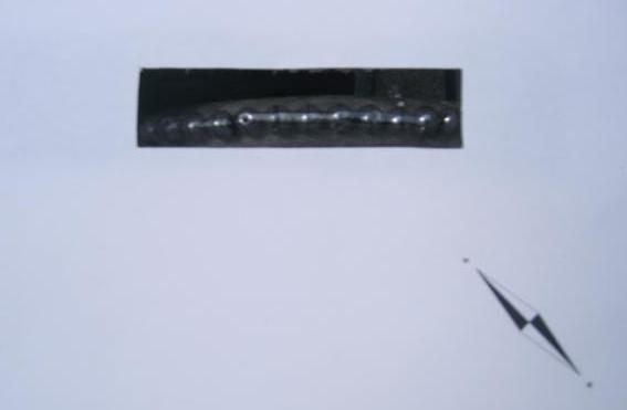
In order to constantly move the spherical magnetic beads to the right, they are placed around the perimeter of a wheel, as in Figure 19, with their North and South poles aligned along the perimeter of the wheel. The wheel is covered with paper and a slot cut so that the wheel can be observed turning and the compass can be centrally aligned with the string of beads. I have not seen this arrangement before in any other publication and so would like to suggest that because Faraday has the Faraday Cage named after him, this wheel could become known as a Highton Wheel. If I am wrong and this has done before, please let me know so I can acknowledge the earlier source.
Figure 19 The Spherical Magnetic Beads are placed around the perimeter of a wheel.
4.6) Placing the Compass Over the Spherical Magnets
A compass is placed centrally over the spherical magnetic beads in Figure 20. (As the camera was operated at an angle to the paper, there is some parallax error making the compass appear to be off centre). With the wheel stationary, the compass aligns along the North-South axis of the string of spherical magnets.
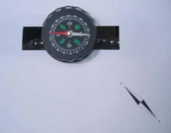
Figure 20 A compass is placed over the Spherical Magnetic Beads.
4.7) Rotating the Wheel
The wheel is rotated such that the top magnets move towards the right-hand side with their South poles at the leading edge. The compass, which is positioned centrally above the wheel, has the North pole of the needle deflected towards the top of the image thus showing that the moving magnets in Figure 21 have the same effect on the compass as the electrons flowing in the wire in Figure 17. In this proposed particle model of electron behaviour, this matching deflection is consistent with the electrons’ South poles leading in a forward travelling wave. This orientation can be reversed when the current flow is reversed during some reflections as we will see later in this article.
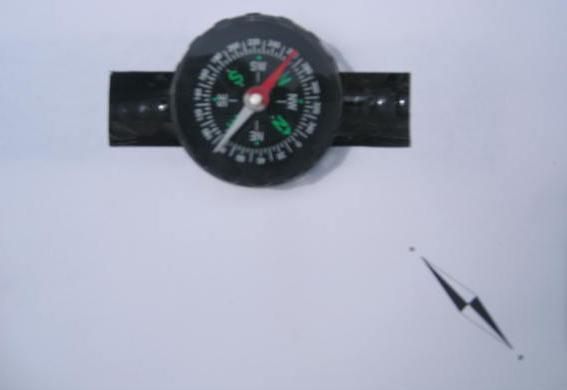
Figure 21 Compass Needle Deflected North by Moving Magnets
Technical Articles Index First Published on 21/10/2026 by William J Highton