3.7) Comparing Current and Voltage Measurements
It is now clear that the toroidal Current measurement is producing a difference measurement as opposed to the Voltage measurement which is producing a sum measurement. This difference versus sum is what causes an apparent phase difference between Voltage and Current measurements but it is more complicated than it appears on the surface. If you look at Figure 6 for the Current measurements, you will see that the Current at the 90° point is a maximum whereas we have just deduced that it should be at a minimum. Similarly, in Figure 5 the Voltage at 90° is at a minimum when it should be at a maximum. There is obviously another mechanism that has to be taken into account and this is related to the properties of the moving electrons in the Transmission Line.
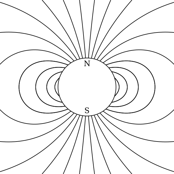
The electrons in a conductor are magnetic dipoles with a North and a South pole as suggested in figure 15.
Figure 15 Charged Particle with North and South Poles
The lines of magnetic flux as indicated in figure 15 are shown in the traditionally accepted form around a spherical magnet, as it would be extremely difficult to measure the exact lines of flux around an individual electron. It is not suggested that an electron is a tiny spherical magnet. However, by using this basic model of a magnetic dipole, we can build an overall model of the electrons in a Transmission Line and test this concept against the plots of Standing Waves.
4.2) Charged Particles Align in Relation to Current Flow
When electrons travel along a conductor in the form of a current, they cause a summed magnetic field which follows Maxwell's Right Hand Grip Rule. As it is difficult to visualise the magnetic field around a conductor built from the lines of flux around individual electrons moving along a conductor, a series of simple experiments can be performed to show the effects of spherical magnets as magnetic dipoles to simulate the behaviour of electrons.
Figure 16 shows a compass which is laid on a sheet of paper. The paper has a compass Rose symbol printed in the bottom right hand corner which is aligned with magnetic North. There are no external magnetic forces other than those from the earth and this figure is intended to display that in later figures the compass is being deflected and is not merely pointing to magnetic North. The North and South markings on the actual compass rose have been ignored during this experiment and magnetic North is maintained with North being to the bottom right hand side of the photograph. This is evident in the direction of the compass shadow caused by the sun, with the experiment being conducted in the Northern Hemisphere at about midday.
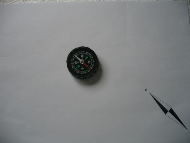
Figure 16 Magnetic North, no Current Present
4.3) Compass Needle Deflection With a Current
Figure 17 shows the same compass placed on a single wire with a conventional dc current passing from right to left i.e. the positive terminal of a power supply is connected on the right hand side of the wire and the negative terminal is connected on the left hand side of the wire, causing the electrons to flow from left to right. The compass is positioned above the wire with the North pole of the needle deflected towards the top of the picture when the current flows, thus showing that the lines of flux follow Maxwell's Right Hand Grip Rule which uses Conventional Current Flow. The compass needle is not fully at right angles to the wire because there is still some influence from magnetic North, giving a resulting vector position, and a higher current would bring the needle closer to a right angle with the wire.
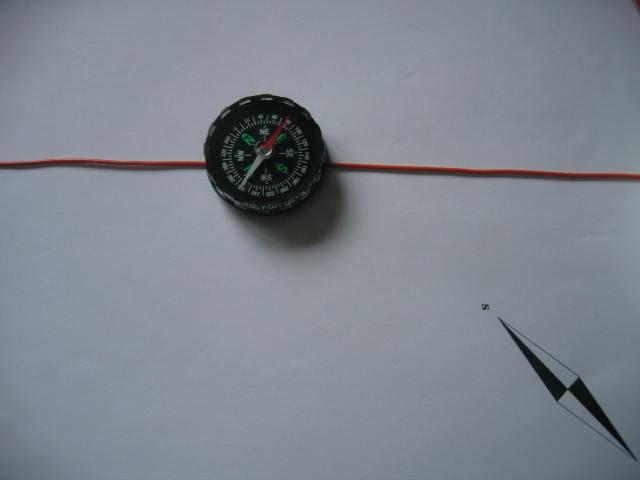
Figure 17 A current deflects the compass needle.
4.4) Compass Needle Deflection With Spherical Magnets
Next a string of spherical magnetic beads are formed into a line and the compass placed above them as in Figure 18. It can be seen that the compass needle aligns with the spherical magnetic beads which have their North poles on the left hand side. It could easily be assumed from this experiment that the electrons in a wire align with their North-South axis across the diameter of the wire because the current passing through the wire in figure 17 causes the compass needle to align at almost right angles to the wire. However this does not take into account that the electrons in the wire move from left to right and therefore the magnets should also move in this direction in order to simulate the electrons flowing in the wire.
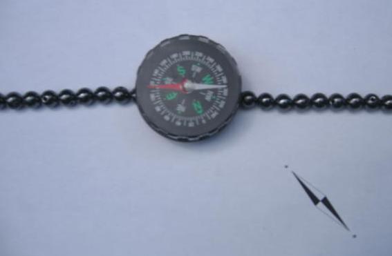
Figure 18 A Compass on a String of Spherical Magnetic Beads.
Technical Articles Index First Published on 21/10/2026 by William J Highton