2.1) Are the Current and Voltage Out of Phase?
By comparing the plots of Voltage Standing Wave and Current Standing Wave in Figure 1, it is now obvious that the two Standing Waves are shown to be 180° out of phase. The classical understanding was that "the Voltage and Current in a Transmission are out of phase", suggesting that the Travelling Waves Voltage and Current were out of phase. We will now analyse this in depth to reach a more enlightening conclusion. The most revealing method for studying the apparent phase difference is to analyse Current flow. As OPEN Transmission lines are no longer generally used and all measurements are either made from a single conductor to ground or a loop around a single conductor, this article will now focus on single conductors similar to the inner conductor of Coaxial Transmission Lines.
2.2) Current flow in a Current Measurement
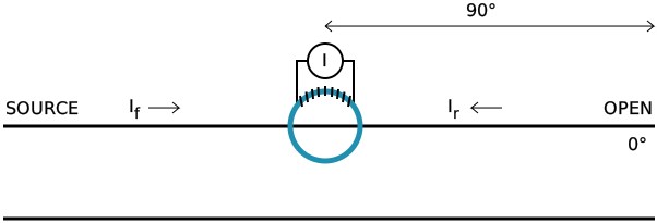
It has already been established that a Forward Wave into a mismatched-termination causes a Reflected Wave and that these Travelling Waves obviously have both Voltage and Current in the Forward and Reflected directions. The Forward and Reflected Currents are shown in Figure 7 as If and Ir respectively. Both of these Currents are shown passing through a toroidal ferrite which is being used as a Current transformer.
Figure 7 showing Current flow in an OPEN Coaxial Transmission Line during a Current measurement
The important observation here is that the measured Currents are flowing in opposite directions through the measurement circuit.
2.3) Current flow in a Voltage Measurement
We again have the miss-terminated Transmission Line but this time a voltage measurement is being performed.

Figure 8 showing Current flow in an OPEN Coaxial Transmission Line during a Voltage measurement
When the Forward Current (If) reaches the Volt Meter a small proportion of the Current in the Forward Travelling Wave (if) is split off and passes through the Voltmeter. Similarly, as the Reflected Current (Ir) reaches the Voltmeter a small proportion of the Current in the Reflected Travelling Wave (ir) is split off and also passes through the Voltmeter in the same direction as the Forward Current (if).
2.4) Significance of Current Flow Differences
It has been demonstrated that the Currents in the Voltmeter travel in the same direction and obviously add, but what happens when two Currents pass through a Current Transformer in opposite directions? Do the Current readings on the measurement equipment add or subtract? This will affect the observed phase difference between the Voltage Standing Wave and the Current Standing Wave and it is essential to have the correct answer to this in order to provide a conclusive analysis.
3.1) Understanding the Current Measurement Method
Confirmation of the interpretation of the Current measurement by a toroidal transformer can be found by making measurements on two separate sample wires with known Current direction and phase. The equipment is connected as per figure 9 and the signal generator set to a low frequency (in this case 1 MHz) in order to minimise problems caused by the screens of the sample wires being discontinuous and also to keep any phase variations to a minimum. Short cable lengths and short sample wires are required in order to avoid significant measurement errors caused by ground discontinuities. The 6 dB Splitter made by Chemandy Electronics is resistive and the phase difference between the two outputs is less than a degree at any frequency less than 1 GHz. The two short coaxial cables connected to the 6 dB splitter output are of the same length. The two short sample wires are also of the same length and just long enough to pass through the toroidal transformer in either direction. With the frequency set at 1 MHz, a difference of 830 mm in the coaxial-cable or sample-wire lengths would give a phase error of one degree and therefore, the phase in the sample wires can be considered as being identical. All inputs to the oscilloscope are connected via 50 Ω terminations and ground continuity is maintained by the RF Bridge coupled output coax. The amplifier used is a 500 MHz Broadband Amplifier.
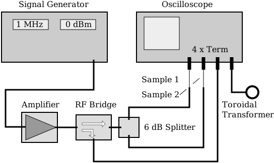
Figure 9 Test Equipment Setup for Current Transformer Measurement
3.2) Confirming the Forward Current
It can be seen from Figure 10 that the top trace displays the Forward Voltage from the Coupled Output of the Directional Bridge and that there is therefore, a Current going towards the two sample wires. The second trace down shows the output from the toroidal transformer into a 50 Ω load and this is not being used at this point. The two sample wire outputs are shown on the lower traces which display the Voltage produced in the terminations by the two Forward Currents and showing that they are in phase.
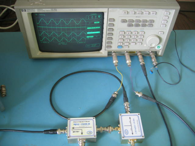
Figure 10 showing the Voltage resulting from the Forward Current
3.3) Confirming no Reflected Current
The bridge is now reversed and it can be seen from the top trace of Figure 11 that there is virtually no signal at the coupled output of the coupler and that there is therefore, no significant Reflected Current from the two sample wires or the splitter. We can therefore be sure that the currents in these sample wires substantially only flow in one direction, from the bridge towards the oscilloscope. The two sample wire outputs are again shown on the lower traces displaying the voltage produced in the terminations by the two Forward Currents and remain unchanged from Figure 10.
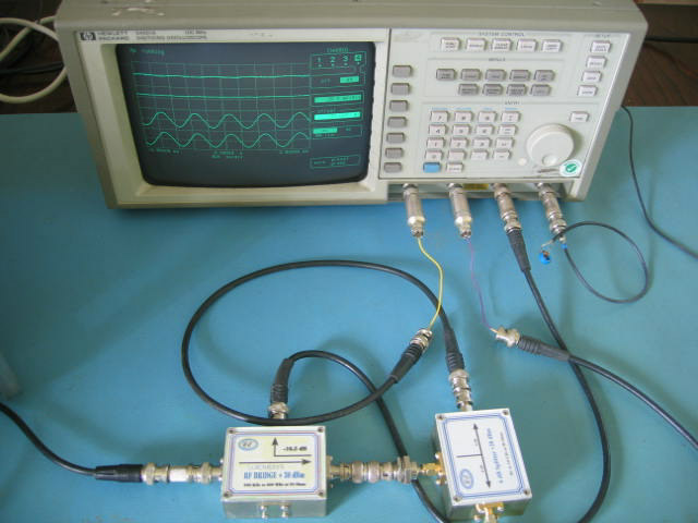
Figure 11 showing that there is no Voltage resulting from a Reflected Current
Technical Articles Index First Published on 21/10/2026 by William J Highton