2.6) Constant Speed of Electrons
Just how does the speed of the electrons in the 'slower' (RG-213) cable as described in paragraph 1.4 get increased again for the second cable (RG-8X). The probable answer is that the electron speed is constant in both cables but the propagation path is longer in the 'slower' cable thus giving a lower velocity. One mechanism for this could be related to the dielectric constant. Let me enlarge on this. If the dielectric causes the electrons to travel in something other than a straight line, e.g. the electrons have to travel around solid particles, then the distance that the electrons have to travel would be proportional to the particle size and density. Thus different dielectrics with different particle sizes and different densities would have different Velocity Constants and therefore different Propagation Times per length. The more dense the dielectric, the lower velocity the electron travels along the length of cable but the electrons speed remains constant.
3.0) Electron Alignment in a Conductor
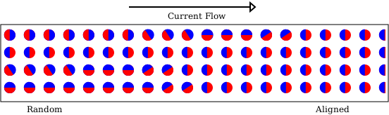
The modern thinking is that each electron is an electric monopole and a magnetic dipole. This causes the electrons flowing in a conductor to all align in one direction, which we have explored in Standing Waves and Reflection. There are several conclusions reached in that article and we add a further conclusion here that is not measurable and therefore is not conclusively proven. However it is important to understand the concept of electron alignment in a conductor in order to understand the following theory of skin effect. Figure 1 is included merely to emphasise the concept of electron alignment.
Figure 1: Electrons Aligning
3.1) Skin Effect
When electrons flow in a wire at high frequencies, it is known that they tend to accumulate near the outside surface of the wire and this is known as skin effect. There are several traditional explanations for skin effect including one explanation that has a higher inductance at the centre of the conductor in relation to the inductance at the surface thus causing a higher reactance at the centre and thus reduced electron flow at the centre of the conductor. Another explanation is that there are eddy currents at the centre of the conductor causing less current to flow at the conductor centre. With the modern view that each electron is an electric monopole and a magnetic dipole, then taking into account that the magnetic alignments of electrons flowing in a wire are all in one direction, which we have explored in Standing Waves and Reflection, then an alternative magnetic and electrical force explanation for skin effect becomes possible. As the electrons across the diameter of the wire at any one point are all at the same electrical potential and magnetic orientation, they repel each other similar to the like charged balls in Coulomb's experiment repelling each other. As the electrons near the surface do not have many electrons pushing them towards the centre of the conductor but are pushed outwards by the electrons in the centre, the electrons are mainly pushed towards the surface. The resultant forces present cause the accumulation of electrons near the surface and probably a smaller collection near the center where the electrons are receiving equal and opposite forces from the electrons just below the surface. This is shown for an alternating current in figure 2 which illustrates that there is a trend for the electrons to travel near the surface of the conductor because of the outward forces present. Of course, there is also the momentum of the electrons travelling along the transmission line which is indicated by the upper arrow. The alignment of the electrons in strings is an assumption and has not been proven.
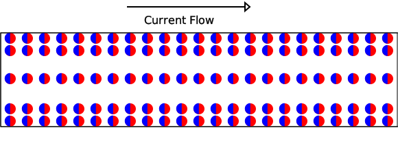
Figure 2 Electrons gathered near the conductor surface
3.2) Longitudinal Forces on an Electron
Figure 3 shows the fundamental force on electrons in one plane travelling along a conductor's longitudinal section without any skin effect. They are evenly spread across the diameter of the conductor and travelling in one direction at the speed of light.
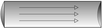
Figure 3 Longitudinal Forces
3.3) Lateral Forces on an Electron
Figure 4 shows the forces in a conductor due to skin effect pushing the electrons towards the outer skin of the conductor. The arrows show the force pushing electrons towards the conductor’s surface.
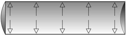
Figure 4 Lateral Forces
3.4 Sum of Forces on an Electron
Figure 5 shows the resultant sum of the forces from the electron travelling along the conductor and the force of the skin effect directing the electrons slightly towards the outer skin of the conductor. There are, of course, fewer electrons in the centre of the conductor due to skin effect.
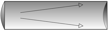
Figure 5 Vector sum of forces
As the sum direction of travel tends to be towards the outer skin of the conductor, some electrons are emitted from the conductor, at a very small angle to the conductor, similar to the radiation from an antenna, in antenna-radiation-elevation-article1.htm However, some of the electrons may be reflected back towards the centre of the conductor and may take a path similar to that suggested in figure 6. This path is longer than the fundamental straight line path shown in Figure 3 and may be another possible reason why the electron takes longer to travel the length of the cable. The electrons are travelling at the speed of light but have a velocity, along the length of cable, of less than the speed of light. The electron velocity was measured in the antenna current-article in the form of a velocity factor of approximately 0.8237 which is an equivalent velocity of 246939047 m/s. The antenna is, of course a vertical equivalent of the illustrated horizontal conductor.
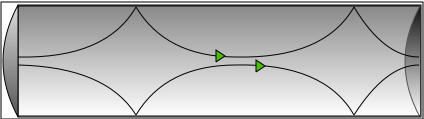
Figure 6 Possible Electron Trajectory
When the path taken by electrons in a coaxial cable is considered, there are probably electrons that are emitted from the centre conductor and then reflected back from the coaxial outer into the centre conductor. The angle of emission from the conductor is increased because of the refractive index of the dielectric being higher than the refractive index of air, giving a path more like the one shown in figure 7, and a higher dielectric constant, and hence a higher refractive index, will give a greater angle of emission.
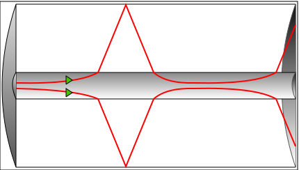
Figure 7 Possible Electron Trajectory Within a Coaxial Cable
The greater angle of emission increases the trajectory distance for the charged particle and hence a longer path in the dielectric. It also means proportionally less time is spent in the lower-resistance conductor and hence greater losses. Simple calculations using the dielectric constant for two different cables showed that the angle of refraction is indeed greater for a higher value of dielectric constant. It is also possible that the circular magnetic field around the centre conductor causes the charged particles to rotate around the outside of the centre conductor during their period in the dielectric but possibly with a much longer length of 'flight'.
3.5) Antenna Radiation
A relevant question arises when the radiation mechanism of an antenna is considered. Just how does an antenna radiate energy over such great distances without any finite material being present? There are several possible behaviours but it is generally considered to be a combination of a moving magnetic and electric field which some authors describe as a series which are alternately collapsing and generating each other and others describe as having equal charges. It is probably described as well as anywhere in Radio Engineers Handbook by F E Terman, McGraw-Hill, 1950 page 770 "Nature of the radiated wave - A radio wave represents electrical energy that has escaped into free space. A radio wave travels with the velocity of light, and consists of magnetic and electric fields at right angles to each other, and also at right angles to the direction of travel. The intensity of the electric and magnetic fields of the wave are such that one-half of the electrical energy contained in the wave is in the form of electrostatic energy, while the remaining half is in the form of magnetic energy".
There is an analogy of the characteristics of a radiated wave in Principles of Radio Communication by J. H. Morecroft, John Wiley and Sons, 1927 page 810 "To illustrate the action let us imagine a gun shooting electrons at high speed, one following another rapidly in the same path, indicated in Fig"7. "Each of these electrons will carry with it its electric field and so at any point in space near the stream of moving electrons (A - Fig.7) , there will exist a moving electrostatic field. But we know that there will be a magnetic field (at right angles to the stream of electrons and also to the direction of the electric field) because this stream of electrons is really an electric current".
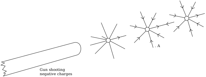
Figure 8 Morecroft's Gun Shooting Electrons
If we compare Terman's Nature of the radiated wave with that of Morecroft's analogy of electrons shot from a gun, it can be seen that in both cases, the electric and magnetic fields behave exactly as electrons passing down a conductor. It was not possible to detect if there were electrons present in a radiated wave when Terman and Morecroft wrote their books. The known method of deflecting electrons to prove that they have mass could only be achieved within a high vacuum such as in a Crookes tube and as J. J. Thomson found, the electrons cannot be deflected if there is an appreciable amount of air. However, it has since been proven that radio waves in space can be deflected and so have mass and must therefore actually be particles. Physicists already know this but it does not yet seem to have dawned on radio engineers. It was not until 1954 that Charles Townes invented the MASER (Microwave Amplification by Stimulated Emission of Radiation) and a fascinating description of how this was achieved can be read in "The Invention That Changed the World" by Robert Buderi, published by Little, Brown and Company 1997 chapter16, "A Sense of God". Once the MASER was available to astronomers, it was easier to observe quasars and pulsars, and studies of these were used to confirm general relativity. In "The Arrow of Time" by Peter Coveney and Roger Highfield, Ballantine Books 1990, page 92 they write "The second result immediately computed by Einstein was the re-calculation of an effect he had anticipated before the completion of his general theory. This concerns the bending of the path of light by matter. One consequence of special relativity and the idea that the speed of light is the same for all observers, no matter what their speed, is the equivalence of energy and mass. Thus there is a mass associated with the energy of light, and this should feel the gravitational pull of other matter; hence the path of the light ray will bend around a massive celestial body like a star". There is a caption to figure 2 (figure 8 in this article) on page 92 which states "Incident light grazing the edge of a star and undergoing deflection through a total angle of 2Φ. (The value of Φ for the Sun has been observed by comparison with known positions of stars during a total eclipse, and more recently by radio observations of quasars approximately in-line with the Sun.)" Buderi's drawing is shown below in Figure 9 and is a very simple concept.
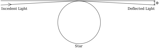
Figure 9 Gravitational Lensing
Further information on Quasars and Gravitational Lensing can be found at http://www.jb.man.ac.uk/booklet/GravitationalLenses.html and http://ned.ipac.caltech.edu/level5/Blandford/frames.html There is much information about the bending of radio waves in books and on the Internet. We cannot perform a simple test with a scope and a DMM on our bench but the evidence that bending exists is currently indisputable.
It follows from the above that if radio waves can be bent by stars and have mass then they must therefore be particles. Also, radio waves and light waves are observed to have different horizons on earth which probably indicates that the particles emitted from antennas are not photons. The suggested mechanism for centre conductors of coaxial cables emitting electrons as per the above velocity factor theory in paragraph 2.3 then becomes applicable to the radiation of electrons from an antenna. The electrons being radiated at the same angle from the conductor as their path within the conductor because the refractive index of the conductor and the outside air are very similar, the result is shown in Figure 5. The difference with the velocity factor explanation being that the antenna attempts to radiate the electrons in two different directions because there are generally two opposite currents (the input current being reflected at the open end of the antenna). This produces a vector sum of the antenna radiations giving an electron stream that varies in angle along the length of the antenna but is at right angles to the antenna at the antenna tip. We can then eliminate the exploding antennas theory and antenna warts problem ( see The Rich Radio Ham Para 1.6) if all charged particles passed into an antenna are emitted. This also removes the need for the idea that the charges pass through the air independently and do not require the presence of an electron. Similar to the findings in the transmission line article 5.9) Relative Phase of INCIDENT and REFLECTED signals in a mismatch where it is shown that the charge remains with each electron as it passes along the transmission line. Of course, if this is the true mechanism of radiation then a very different method of calculating radiation is required from the present ones and would probably include some form of Radiation Work Function, which would be dependent on the material and its surface that is used. Whether this would result in a Radiation Resistance as per present calculation methods is rather uncertain, but certainly most of the present antenna formulas would become redundant.
Radiated electrons make the whole behaviour of an antenna easier to understand. The inductive field (near field) is simply the electric and magnetic fields produced by the electrons within the antenna and the radiated field (far field) is the field produced by the electrons that are radiated. It then becomes clear that antennas can only transmit over any appreciable distance by radiating electrons but can receive by interaction with the electric or magnetic fields of any radiated electrons, or by absorbing the actual electrons themselves. Therefore the transmit antenna has only one transfer mechanism and the receive antenna can be any combination of three, thus making the theory of antenna reciprocity rather suspect. All of this suggested antenna theory is based on actual measurements made in antenna radiation and antenna current distribution which were performed in a logical progressive manner, with dedicated test equipment by a very experienced engineer and there seems to be very little chance of error. If all of these conclusions are correct, then this would make the presently accepted antenna theory in our text books wrong and even some accepted facts about light become suspect. The behaviour of electrons is therefore much simpler than present accepted theory states!
Technical Articles Index First Published on 21/10/2026 by William J Highton